


This article will present technical data to support the authenticity of an Original Series communicator hand prop that has been in my memorabilia collection since February 1998. This communicator has been in my possession continuously for the last 10 years with the exception of an 8 month time frame between 7/06 and 3/07; during which it belonged to a well respected Star Trek expert and private collector who performed a slight refurbishment to the prop by removing excessive glue deposits between the top plastic vacuuform shell and the aluminum midplate which considerably improved the aesthetic appearance of the item. The collector indicated that the refurbishment was performed on a recommendation from renowned Star Trek collector and model maker Greg Jein, who viewed photos of the communicator around August 2006 and mentioned that the excessive glue deposits which were clearly present on the piece were indicative of a repair operation being performed at some point during production, and were possibly indicators of multiple repairs. It was mentioned that Greg Jein himself has trimmed excess glue from a couple of items in his Original Series collection which were untidily reassembled after repair and has even repainted TOS props to subtly restore them to their original production state without fear of adversely impacting their intrinsic value.
The photograph below shows the appearance of the communicator prior to the slight restoration operation as well as its current appearance.

AUTHENTICATION ITEM 1: Evidence of Production Repairs Performed. As Greg Jein indicates, messy or excess glue deposits are not a disqualifier for prop authenticity. In TOS they would imply production repair activity. A close examination of the glue visible in the side view photo above clearly shows 2 different adhesive colors (a dark and a much lighter shade of glue) implying 2 different times that the communicator was opened for repair).
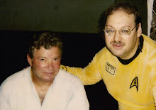
Presented below is a photo of my communicator with the one that is currently part of the Paul Allen Collection – currently on public display at the Science Fiction Museum in Seattle, WA. This photo was taken in the home of Star Trek (1966-1969) Set Decorator John Dwyer.
Photo A:

Photo B:

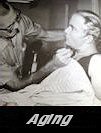
Expected evidence of age on brass antenna components observed to be consistent between Allen and Gurian communicators. It is quite evident when considering the following closeup view of the communicators side by side that the bronze colored wheels of the antenna assemblies and the visible portions of the antenna mesh and frame on both pieces have identical tarnish discoloration and signs of aging, with a somewhat darkened patina. Antenna aging should not be considered a disqualifier of prop authenticity; but is a naturally occurring phenomena on TOS items from the ‘60s. The degree of aging would be significantly affected by the storage conditions (eg. Shoebox versus Garage) and other considerations such as climate and humidity. The Allen and Gurian pieces demonstrate equivalent storage conditions.
Photo C:

Photo B was selected to provide a baseline reference measurement on the size difference between the Allen and Gurian communicators. Even though the photo is not an ideal top or plan view but rather shows the props from an angled perspective; this photo can be trusted to provide a reliable reference since:
- The 2 communicators are placed side by side very close to one another, with approx. one-third of an inch or less total distance separating them
- A measurement may be made on each piece of the total length of the top black plastic shell: starting at a common reference location (right at the point where the shell edge line intersects the outside bronze wheel surface) extending along a dimension line to the other end of the shell where the boundary line between the black plastic of the vacuuformed piece meets the aluminum midplate.
- The measurement lines on each communicator can be made along lines parallel to the center lines of each piece for added accuracy; and
- Since the measurement lines are physically located very close to one another spatially, (near the surfaces of the two props that are separated by just a fraction of an inch), the effects of measurement distortion due to perspective will be negligible.
The following annotated photograph was produced using a computer-aided design (CAD) software to automatically measure the length of the shells. Note that the photo was intentionally left unitless, so that the values listed would enable a direct comparison of the size of the two pieces; but would not necessarily reflect actual distances in British or Metric units.
Photo D:

AUTHENTICATION ITEM 3:
The above baseline length measurement of the Allen and Gurian communicators, determined from a photo of both pieces sitting side by side, establishes an identical length for the black vacuuform top shell; which is an important validation milestone.
The next series of measurements was taken on a composite photo; consisting of an image of the Allen communicator on display at the Museum of Science Fiction in Seattle, and an image of my communicator which was held at a slightly declining angle away from the camera to simulate the vertical position of the Allen prop. (My dog insisted on participating in this photoshoot!) The images of the communicators were scaled so that one measurement – the vertical height of the brass antenna – would be equal. (The excellent vertical alignment of the antennas in the photos greatly facilitated correct scaling.) Several other dimensions were then generated with the CAD software to provide insight on the relative sizes of several other components of the two props.

AUTHENTICATION ITEM 4:
Using a scaled composite photo, 5 different subassembly lengths are found to be identical between the Allen and Gurian communicators.
With confidence that my piece was dimensionally correct with a very high degree of precision, I then turned to the filmed footage of The Original Series to determine if I could detect in the episode screenshots any unique design characteristics or construction details onscreen that perfectly matched the appearance of my prop.
When considering which design characteristics were most likely to have remained undisturbed over a 40 year period since the last TOS episode was filmed; I considered the condition in which the surviving communicators with impeccable provenance were recently photographed/documented.
It is known that the Allen communicator had lost 2 jewels by the time it was placed on display in the Seattle museum in the 2002 time frame. One of Greg Jein’s communicators (Epsilon), which has since been refurbished, was missing the right knob from its control panel and had a misaligned moiré pattern. Another Jein communicator, (Zeta), was observed to have its colored jewels just pushed into place in their bezels and not permanently affixed. These jewels could easily become lost or misplaced if the communicator were tossed about on a sound stage. Additionally, a communicator shown in what is believed to be a third season outtake photo (known as the Kious photo) was observed to have a torn moire. The following photo shows the unrefurbished appearance of the Allen and 2 Jein communicators …

The photo below of the disassembled top shell of Jein Comm2 reveals that, on this piece, the silver metal moiré ring or bezel was actually embedded into a perfectly matching sized hole cut into the shell. My communicator also features this design characteristic; though, this is not sufficient evidence to suggest that all authentic communicators were constructed this way. A much larger sample set would be needed in order to draw any meaningful statistical inferences.

Screenshot Studies:
After approximately a dozen attempts, I succeeded in photographing my prop so that the spatial orientation of its plastic body was almost identical to that of a TOS communicator observed to have a very similar moiré pattern in the 2nd season episode “The Omega Glory”. (It proved too difficult to also orient the brass antenna at a perfectly matching angle to the screenshot.) As was done earlier with the Allen communicator, a composite photo was created and CAD software was used to take a series of reference measurements. The photo is displayed below …

I was surprised to see that all 7 reference measurements came out identically. The distances examined were:
- The width of the aluminum metal midplate.
- The width of the left brass antenna wheel.
- The length of the aluminum metal midplate. (Not a true length since the plate is tilted forward in the photo, but a linear dimension on the page.)
- The height of the moiré bezel as measured from its visible boundary next to the black shell body.
- The height of the metal control panel.
- The width of the microphone grill.
- The distance between the top of the moiré bezel and the beginning of the rounded edge of the black shell. Measured at 0.29 units.
Note 1: It was remarkable that Distance 7 turned out identical since the location of the moiré on the front shell of the communicator would be subject to manual assembly variation (the propmakers seemed to try to similarly locate these on the flat upper half of the shell; but such a precise match to a screenshot was unanticipated.) A example of some of the variation to be observed in the placements of the control devices such as knobs, jewels and moiré bezels is seen in the photo below of the Alpha and Zeta communicators.

Note 2: Also remarkable was the identical measures (and thus an identical ratio) observed on the width of the aluminum cutout for the microphone grill versus the width of the aluminum control panel. On both the Omega Glory screenshot and my piece, grill widths of 0.49 and panel widths of 0.70 were observed, for a ratio of 0.49/0.70 = 0.7 exactly. These relative sizes (the ratio) are visually observable to vary sometimes significantly between the screen-used pieces. As an example, consider the Allen and Jein communicators in the following measured photo.

Some further remarkable matches in what might be considered to be construction errors or slight misalignments during fabrication are also observable on the screenshot communicator and my prop. If these are not deemed significant enough tells to establish a positive id of my plastic shell and antenna wheel mechanism with the screen-used prop; then they are certainly extremely powerful evidence of the work of the same craftsman/propmaker.
Specifically, as highlighted in the photo below …
- Both props witness the same misalignment in the mounting of the brass rotating antenna wheels into the aluminum midplate, with the right-side wheel appearing to be slightly higher (and closer to the top edge of the communicator) than the left-side wheel
- The serrated edgeline of the bottom of the punched antenna plate itself is observed to be inclining slightly upwards at an angle of 3 to 4 degrees on each piece; its angle influenced by the improper mounting of the antenna wheel assembly.
- The contour of a jagged cutout in the black plastic shell by the left-side antenna wheel; allowing the wheel to be mounted to the midplate is virtually identical on the two pieces.
Another interesting observation is that the screenshot communicator clearly has much less aluminum midplate showing in its upper left corner and side than my communicator; however, it is evident that the top plastic shell of my prop has been reseated (possibly twice) on the midplate for repair operations, as confirmed by the different colored remnants of glue which were present on it; so its original orientation on the midplate might easily have been less skewed to the right, and been consistent with the screenshot orientation. Very importantly, a correct repositioning of the shell to match that of the screenshot would necessarily push it up towards the top edge of the midplate, and all of the silver metal visible through the plastic shell cutouts for the wheels would be hidden when the communicator is posed correctly for the screenshot.
It is further noted that the angle of incline of the brass antenna was not perfectly replicated between the modern-day and screenshot images of the prop – only the orientation of the shell was closely matched. This could easily explain the slight difference seen in the measured angle of the serrated antenna edgeline.

AUTHENTICATION ITEM 5 OMEGA GLORY SCREENSHOT COMPARISON
- 7 identical measures on distances of major components and offsets of components from each other
- 3 of these were not expected to be perfect matches to Omega Glory screenshot given variation in assembly observed between other screen-used communicators (Specifically, vertical offset of moiré bezel on top shell, width of microphone grill, and width of aluminum control panel plate).
- Remarkable match on vertical misalignment in mounting of antenna wheels to aluminum midplate, with right side wheel higher in communicator body
- Remarkable match in jagged angular cutout of plastic shell for placement of left wheel
- Near identical slight incline observed to serrated edgeline of antenna mesh. Difference of 1 degree could be attributed to incomplete rotation of antenna in modern-day photo
Technical Aside: Why the Communicator in the Kious Photo is not reconcilable to the Omega Glory screenshot.
Some collectors might be aware of a well distributed image, speculated to be a 3rd season production outtake shot, of a different communicator featuring a slight “haircell” textured pattern on its black shell (versus a smooth surface vacuuform shell) and a similarly designed moiré pattern to that of the Omega Glory screenshot.
This piece is shown below next to the Omega Glory screenshot. On detailed inspection, there are several fixed construction characteristics of the “Kious” communicator (the name by which it is known) which virtually rule it out as a candidate for the prop appearing in the Omega Glory scene.

An Additional Note on Light Reflection Characteristics Observed On The Omega Glory Communicator (and Smooth Bodied versus Textured “Haircell” Pattern Bodied Vacuuform Shells)
The communicator used in the Omega Glory screenshot, also believed to be the same communicator that is present in the additional TOS screenshots from “Tomorrow Is Yesterday” and “Assignment: Earth” displayed later in this article; appears to be a smooth body shell communicator. Well respected Star Trek prop expert Richard Coyle, who designed and created hand props for the Star Trek feature films, notes in a technical article entitled “Star Trek, Classic Communicators” on his website http://www.racprops.com/ that “There were essentially three body styles: the full textured; the lightly textured, which was a full textured body that was either well worn or intentionally sanded to nearly smooth; and last, the completely smooth body.” In the following composite image, I photographed a 1970’s era fully textured vacuuformed communicator from my collection at distances of approximately 1 foot, 2 feet, 3 feet and 4 feet from a digital camera with flash active to study the reflected light patterns visible on the patterned plastic shell. It seems quite evident to me that the fully vacuuformed shell, even when photographed at distances greater than that used in the Omega Glory and other TOS screenshots, demonstrated a striking splotchy pattern of reflected light with many noticeable “pin-pricks” or tiny concentrated points of high illumination that was markedly different than the smoother, more fluid reflective patterns seen in OG and other screen captures.


Specifically, as highlighted in the following photo containing the screenshot image and some perspective views of my communicator:
- The “Tomorrow Is Yesterday” prop has a unique light reflection signature on the left side of its brass antenna mesh (the right side in the screenshot) due to the presence of silver colored solder that was applied to hold the perforated mesh to the thin cylindrical rod that acts as the frame for the antenna. There appears to be 2 very distinct triangular-like patterns of reflection off of the solder in the screenshot that are perfectly matched by solder patterns on my communicator.
- Also, in the screenshot, the contours of the serrated top edgeline of the brass antenna mesh are clearly visible, showing exactly 11 cut holes with perhaps 20% to 30% of the hole circumferences remaining. This unique pattern is also found on my communicator.

In the photo below, one can get a better feel for the curvature associated with the transition from the top mesh to the sides.


- The appearance of the serrated antenna mesh edgeline on the Gurian communicator, featuring 11 holes with 20% -30% circumference visibility was seen to match that in the “Tomorrow Is Yesterday” screenshot prop
- Also, the TIY screenshot appeared to have a light reflection pattern on the left side brass antenna mesh that matched the outside solder pattern on the Gurian piece
- The Assignment: Earth screenshot showed a faintly visible discoloration near the bottom end of its left side antenna mesh that matched an inner solder joint configuration on the Gurian communicator in that same location, as well as showing the correct outside reflective patterns
Regarding the back side of the communicator, I believe the configuration of my prop is a very precise match, including some identical unique construction flaws, to the one seen in the episode “Return to Tomorrow”. When such minor assembly flaws discernible on a screenshot are matched so perfectly to a prop in one’s hand, it is indeed an incredibly exciting experience!
The composite photo below highlights the numerous matching characteristics between the screenshot and the Gurian communicator, including:
- Equivalently sized and placed Velcro backings.
- Identical right corner slight protrusion (cutting error) on Velcro matt
- Identical left corner Velcro wear revealed to be imbedded fiber/torn material error
- Matching lumpy deformation at bottom center of Velcro matt reveal to be slight glue seepage onto back shell

- A match between the screenshot and the Gurian communicator was obtained with regard to the size and placement of the large Velcro matt affixed to the rear shell
- 3 different construction flaws, 2 associated with Velcro cutting and one with slight glue seepage, were matched on both pieces
CONCLUSION
In summary, over the course of this article, my communicator was demonstrated to be dimensionally identical with another surviving TOS communicator prop (the Allen comm) with respect to the key vacuuform shell, brass antenna and other subcomponent size measures that one would expect to remain consistent between the pieces; and approximately 17 matches were found on my piece to TOS episode screenshots of communicators (both dimensionally and assembly related), some startling and unanticipated. Several might even be deemed sufficient to establish a perfect match with a particular on screen prop; but together, all of the visual screenshot evidence and construction details observable certainly confirms, in my opinion, that my communicator is an authentic vintage Star Trek prop created by the same propmakers employed by Desilu on TOS. This article should serve to technically enhance the opinion offered by Set Decorator John Dwyer when this prop was photographed with the Allen communicator in his home that both pieces are original Star Trek hand props.